
Safety Engineering · 9 min read
How a kinetic LED wall safety system should work.
A moving LED wall needs a defined stop path, position limits and recovery procedure—not just a larger motor and a remote control.

A kinetic LED wall is a machine carrying a display. It has moving mass, stored energy, pinch points, cables, control software and people working nearby. The safety system has to bring those parts into one predictable operating boundary.
The useful question is not “does it have an emergency-stop button?” It is “what happens when a person presses it, a limit is reached, a sensor fails or communication is lost?” Those states should be defined before the mechanism is released for production.
Start with a controlled stop path
Every motion route should have a documented stop path from the operator input to the drive and mechanical movement. The exact architecture depends on the axis count, drive selection, risk assessment and local installation requirements, but the project team should be able to trace the sequence.
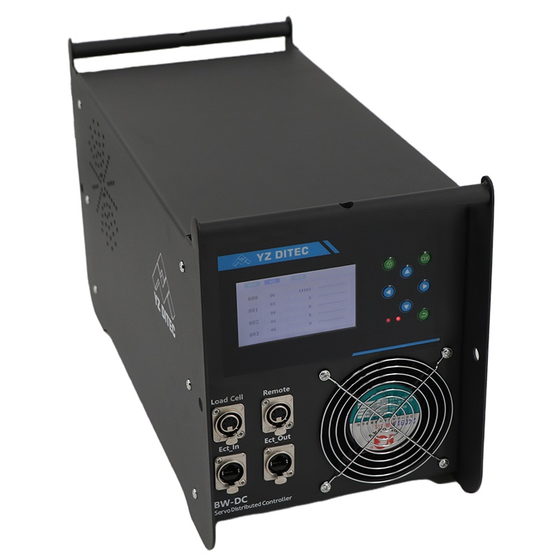
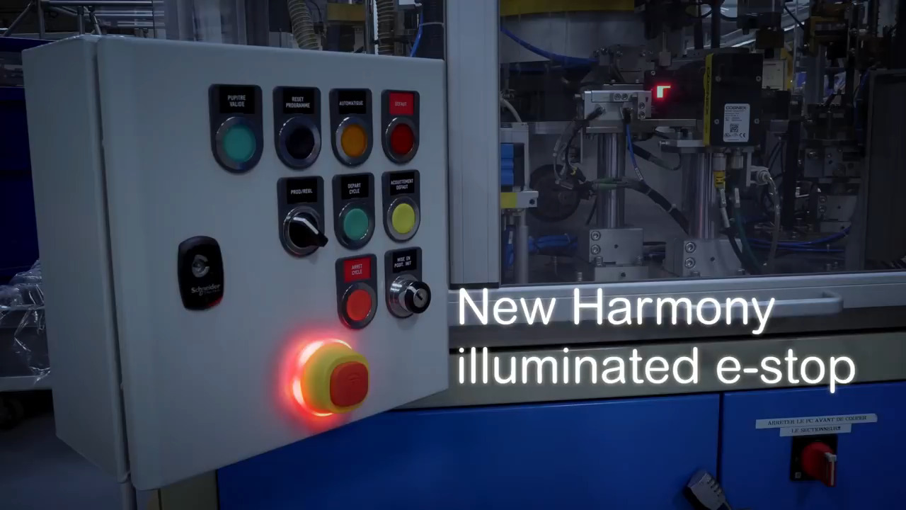
An emergency stop should remove the commanded motion and leave the system in a known state. Whether the brakes hold immediately, the axes coast to a controlled stop or the complete system disables depends on the machine design. The quotation and FAT plan should state what the operator will see and what must happen before restart.
Five protection layers to define
| Layer | Purpose | What to confirm |
|---|---|---|
| Emergency stop | Stops commanded movement during an abnormal event. | Button locations, stop behaviour, reset and restart conditions. |
| Travel limits | Prevents an axis from moving beyond its permitted range. | Hard limit, software limit, limit access and fault indication. |
| Position feedback | Lets the controller know where the mechanism is. | Homing method, encoder status, loss-of-position response and re-zero procedure. |
| Pinch and collision control | Protects people, panels, cables and adjacent structures. | Guarding, clearance, sensors, reduced-speed setup and obstruction response. |
| Restart interlock | Prevents an unexpected movement after a fault or power return. | Manual acknowledgement, safe state and conditions for re-enabling motion. |
These layers are not interchangeable. A software limit does not replace a physical travel limit, and an emergency stop does not prove that the mechanism can be safely accessed while powered. The final arrangement should be reviewed against the actual moving geometry.
Limits and homing are part of the show workflow
Operators often think about the normal show position first: open, closed, raised, rotated or parked. Engineers also need the positions between those states. Define the home position, working limits, service position and recovery position. Each one should have a clear label and a reason for existing.
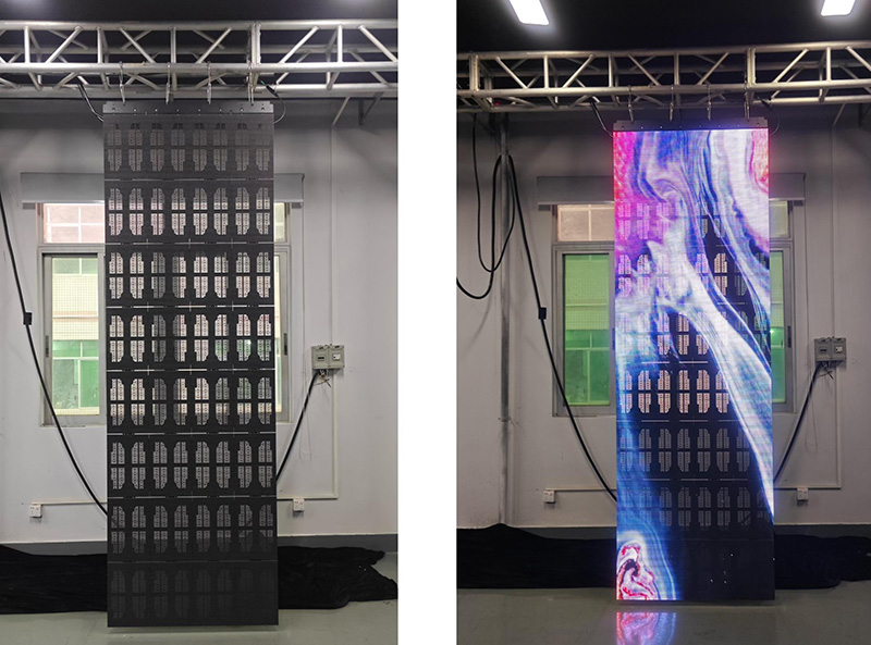
For a multi-axis wall, decide whether one axis fault stops every axis or only the affected group. A synchronized movement may require a system-wide stop even when the original fault is local. That decision belongs in the motion sequence and the operator instructions, not in an informal handover conversation.
Design around the real pinch points
Pinch points are created by geometry, not by the product name. Look at folding hinges, telescopic gaps, sliding carriage interfaces, rotating edges, cable loops and the clearance between the LED face and a fixed wall. A static photograph rarely shows the full hazard envelope.
Mark the keep-out area on the layout drawing. Identify where an operator may stand during setup, where a technician needs access for service and where a venue audience must never enter. If the project uses barriers, floor markings or a local guarding system, show the interface and responsibility clearly.
What to test before shipment
A factory acceptance test should include normal operation and intentional faults. The buyer and supplier can agree the exact test method, but the checklist should cover at least:
- Power-up and homing from a known safe condition.
- Each emergency-stop station and the required reset sequence.
- Every hard and software limit, including the displayed fault state.
- Loss of encoder, sensor or control communication, where applicable.
- Power interruption and return-to-service behaviour.
- Reduced-speed setup or service mode, if provided.
- Restart prevention after an obstruction, limit trip or emergency stop.
Record the configuration revision, test witness, result and open action. A video of the mechanism moving is useful evidence; it is not a substitute for a signed safety response checklist.
Confirm the site interface before installation
The supplier cannot define the complete safety boundary without the site information. Share the screen size and moving load, the travel path, ceiling or floor constraints, operator location, audience access, local power arrangement and any venue interlock requirement. Also state whether the site team or the supplier provides barriers, lifting equipment, structural verification and final commissioning.
Next step
Send the intended motion, approximate screen size, project location and a sketch of the keep-out area. Joeqing can then review the motion family, control boundary, safety interfaces and the evidence required at factory acceptance before a quotation is finalized.
Need to review a moving display safely?
Share the motion path, moving load, access conditions and target site.