
Home / Projects / Outdoor Rotating Landmark Project
Three rotating LED layers, engineered as a public landmark
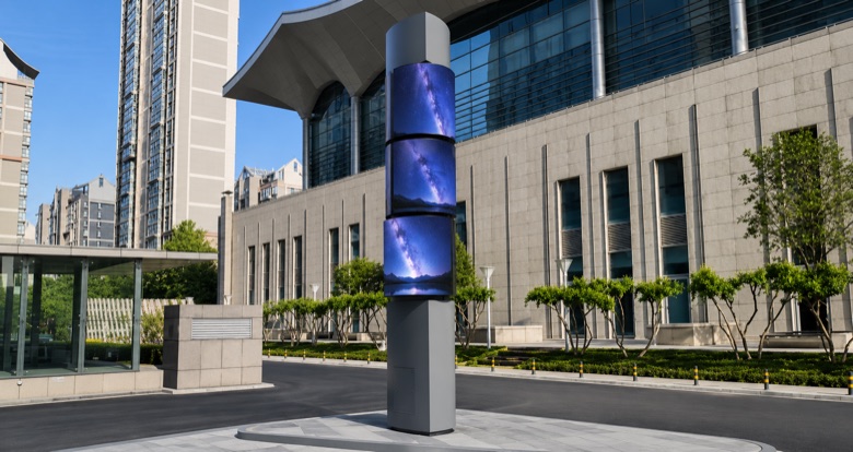
An outdoor P4 installation in Xi’an with three independently servo-driven layers — where continuous rotation, wind exposure and a foundation interface all sit inside one engineering boundary.
Project at a glance
- Delivered
- March 2026
- Location
- Xi’an, China
- Display size
- 6.27 × 4.8 m
- Display spec
- Outdoor P4
- Layers
- 3, independently servo-driven
- Drive
- 1500 W servo per layer
- Structure
- Galvanised Q235B steel
The brief: outdoor rotation changes every boundary
Take a rotating LED tower outdoors and almost nothing carries over unchanged. Wind exposure becomes a structural case. Power and signal have to cross a continuously rotating joint. Corrosion protection stops being a finish and becomes a specification. Maintenance access has to work at height, outdoors, on a structure that turns.
None of those are display problems. They are the reason an outdoor kinetic landmark is engineered against the actual site rather than selected from a catalogue.
What was engineered
Structure
The reference build uses a galvanised Q235B steel framework with a central shaft and fabricated flanges, on a project-defined supporting structure. Galvanising is not cosmetic here — an outdoor rotating assembly cannot be taken down easily for remedial work.
Independent servo-driven rotation
Each of the three layers rotates on its own 1500 W servo, following the approved synchronised, counter-rotating or offset sequence. Reference position accuracy is ±0.1 mm with a control update of under 20 ms — the numbers that decide whether a multi-layer composition holds together or drifts.
Continuous rotating power transfer
A custom slip-ring route carries power and signal across the rotating boundary. Continuous rotation rules out any cable-managed solution: the joint has to work indefinitely, outdoors, without a service interval that requires shutting the landmark down.
Wind, foundation and access
Wind pressure, extreme weather, seismic conditions, foundation capacity, display weight, rotational inertia, braking and maintenance access are reviewed together, not in sequence. Rotational inertia in particular is easy to underestimate — it drives both the drive sizing and the braking case.
| Reference value | Figure |
|---|---|
| Overall display size | 6.27 × 4.8 m |
| Display specification | Outdoor P4 |
| Rotating layers | 3, independently controlled |
| Drive per layer | 1500 W servo |
| Position accuracy | ±0.1 mm |
| Control update | Under 20 ms |
| Framework | Galvanised Q235B steel, central shaft and fabricated flanges |
Reference values from this configuration. Final figures are engineered against the actual site, wind-design basis and installation method.
Delivery
Foundation interface and service access are confirmed early, because both are expensive to change once steel is fabricated. The final landmark is engineered against the real site conditions rather than against a standard drawing.
Questions this project usually raises
What wind design basis do you need?
The local wind pressure and extreme weather data for the site, alongside seismic conditions and foundation capacity. Those four inputs, with display weight and rotational inertia, set the structural case before any drive specification is fixed.
How does power reach a continuously rotating display?
Through a custom slip-ring route that carries power and signal across the rotating boundary. Continuous rotation rules out cable-managed alternatives, so the joint is engineered to run indefinitely outdoors.
Can the layers rotate in opposite directions?
Yes. Each layer is independently servo-driven and can follow a synchronised, counter-rotating or offset sequence according to the approved programme.
Why galvanised steel rather than a painted finish?
Because an outdoor rotating assembly cannot easily be taken down for remedial work. Corrosion protection is treated as a specification with a service life, not as a surface finish.
Related
Planning an outdoor moving landmark?
Send the location, target size, wind-design basis, support concept and LED scope. Engineering replies within 8 business hours.
Start engineering review