
Facade Engineering · 10 min read
Kinetic facades: how the movement is actually driven.
Most kinetic facade references show the effect. Before you can specify one, you have to answer a narrower question—what moves the elements, and what happens to that mechanism in weather, over years, at height.
A kinetic facade is a building envelope whose elements change position. That is the whole of the definition, and it is why the category is so hard to price: it covers a shading fin that rotates twice a day and a display surface that moves continuously during an event, and those two things share almost no engineering.
The useful first question is not what the facade looks like. It is how the movement is produced, because that single decision sets the load path, the power and control scope, the maintenance regime and most of the cost of ownership.
Two ways a facade moves
Broadly, kinetic facades split into passive and driven systems.
Passive systems take their energy from the environment—usually wind. The elements are hinged or suspended so that airflow moves them. There is no motor, no cabling and no control system on the facade itself. The movement is genuinely unpredictable, which is the point: the building reads as alive without anyone operating it.
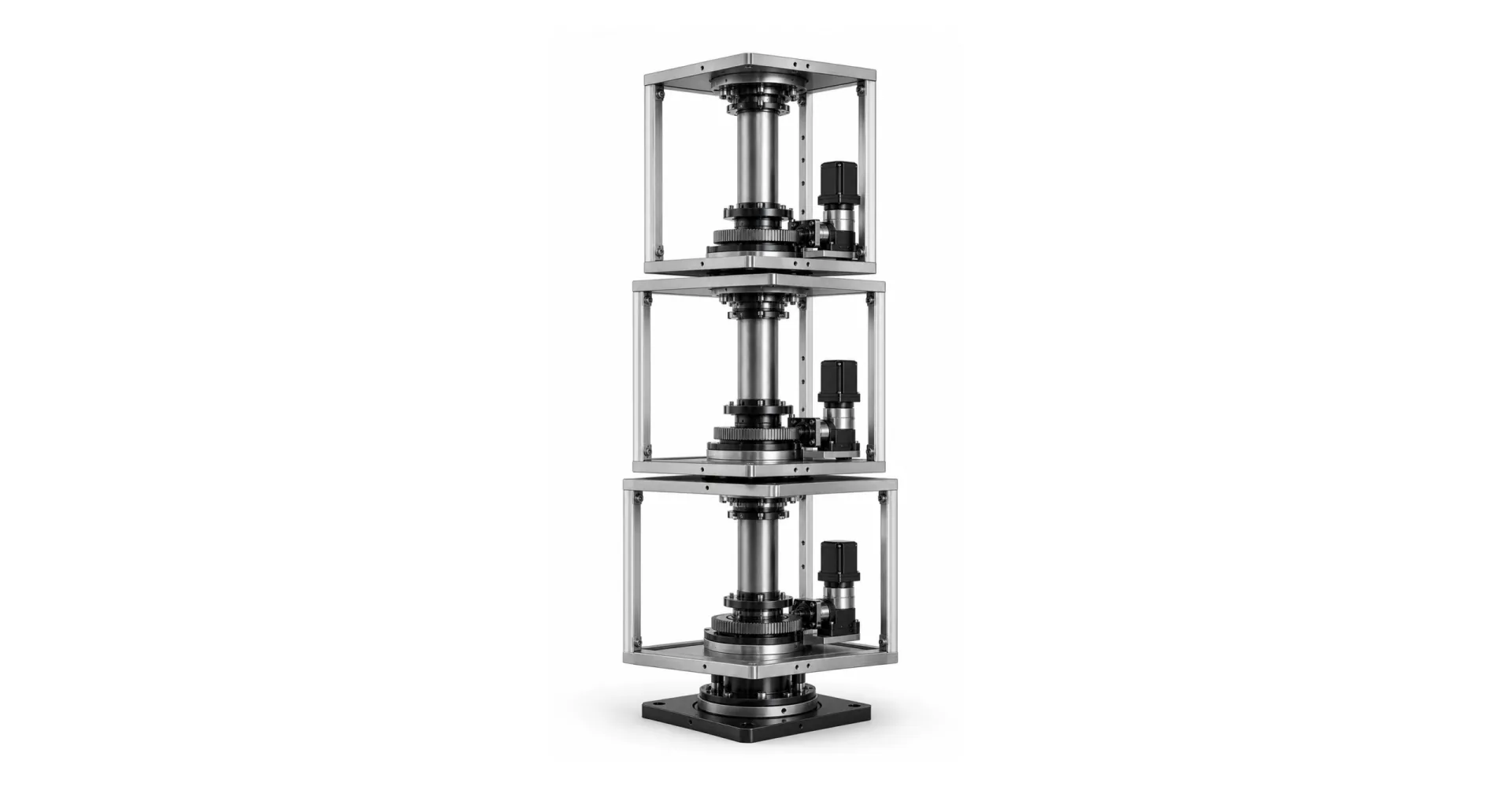
Driven systems move elements with motors or actuators under control. Position is commanded and known. The facade can hold a state, repeat a sequence, respond to a schedule or a sensor, and—when the elements carry displays—coordinate movement with content.
These are not competing versions of the same product. They answer different briefs.
| Passive / wind-driven | Driven / motorised | |
|---|---|---|
| Movement | Depends on weather; cannot be commanded | Commanded, repeatable, position-known |
| Power and data | None at the facade | Power, control and often video to every moving element |
| Structure | Carries wind load and element self-weight | Also carries drive reactions and dynamic loads from starting and stopping |
| Failure mode | Element detaches or fatigues | Element detaches or fatigues, plus drive, control and cable-management failure |
| Maintenance | Inspection of hinges and fixings | Inspection plus drive servicing, lubrication and control checks |
| Suits | Texture, shading, a building that should feel animated | Content, choreography, anything that must be on cue |
If the brief contains the words “on cue”, “sequenced”, “synchronised with” or “shows content”, the passive route is already out. Everything below concerns driven systems.
Wind is the governing load, not the motion
The intuition that trips up early-stage design is that the moving parts are the demanding part. In a facade they usually are not. The motion is slow and the moving mass is modest compared with what wind does to the same surface.
Wind governs in three separate ways, and they need separate answers:
- Load on the element in every position. A panel that rotates presents a different area to the wind through its travel. The worst case is often not the closed position that gets drawn.
- Load transmitted back into the drive. A gust acting on a panel applies torque to whatever holds it. The mechanism has to resist that while stationary, not only while moving.
- A defined safe state. Above a wind threshold the facade should move to a parked position and stay there. That threshold, who measures it and what happens if the measurement fails are project decisions, not supplier defaults.
The practical consequence: a kinetic facade needs a wind study in the same way a conventional facade does, and the movement envelope has to be an input to it rather than something added afterwards.
Access decides the cost of ownership
A mechanism at ground level is serviced by a technician with a ladder. The same mechanism at forty metres is serviced by a rope team or a building maintenance unit, on a permit, in a weather window.
This is the single largest difference between a kinetic facade and the kinetic installations that go inside lobbies and stages, and it deserves to be settled early:
- Can a drive unit be replaced from inside the building, or only from outside?
- Is any element serviceable individually, or does one failure take a bay out of service?
- Where do the consumables sit—bearings, seals, cable carriers—and what is their expected interval?
- What does the facade look like with one element parked for service? If that state is unacceptable, redundancy has to be designed in, not negotiated later.
Designing for access changes the mechanism. It is cheaper to decide it at concept stage than to discover it at handover.
Outdoor duty is a different specification
An indoor kinetic installation runs in a controlled environment. A facade does not. Drives, bearings, cable management and any electronics face water, dust, temperature swing, UV and—near coasts—salt. Ingress protection ratings, material selection and sealing details belong in the specification from the start, because retrofitting them is usually impossible.
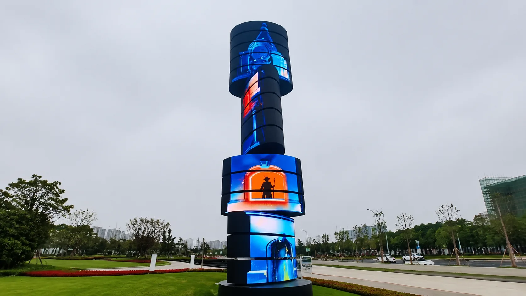
Where the moving elements carry LED, the display and the mechanism have separate environmental requirements and separate power budgets. Servo or motor power is additional to the display load. On our outdoor rotating landmark platform, for example, the drive is specified at 1,500 W per rotating layer across three layers, independent of whatever the LED itself draws. Any electrical allowance that counts only the display will be short.
A facade moves over people
Most kinetic facades sit above public space. That pulls the safety case away from machine-guarding conventions—you cannot fence the area—and toward containment and predictable stopping.
The questions to settle:
- What is the stop path, and does the facade stop safely on loss of power rather than coasting or falling to a lower position?
- Is every moving element mechanically retained independently of the drive, so that a drive failure cannot release it?
- How is position sensed, and what does the system do when position feedback disagrees with the command?
- Who is authorised to move the facade, and how is movement locked out for maintenance and for adjacent trades?
These are the same principles that govern a moving display indoors, applied where the consequence of getting them wrong is larger. We covered the underlying logic in how a kinetic LED wall safety system should work; for a facade, add the public-space case and the fact that nobody can reach the mechanism quickly.
What to fix before you specify
A kinetic facade can be quoted meaningfully once these are defined. Before that, any number is a guess.
- Motion — what moves, through what travel, and how fast.
- Element — size, weight and whether it carries a display.
- Trigger — schedule, sensor, operator or show control.
- Site — height, exposure, wind data, seismic requirement, coastal or not.
- Access — how a technician reaches a drive, and under what permit.
- Interface — where the supplier’s scope ends and the main structure, power and BMS begin.
- Safe state — the parked position, and the conditions that command it.
The last item is the one most often left open, and the one that most often changes the mechanism.
Where the boundary usually falls
On facade projects the mechanical scope is rarely the whole job. The realistic split is that the structure, cladding and building services stay with the main contractor, while the motion structure, drive, control boundary and the evidence that the movement is safe come from a motion supplier. Setting that boundary early is what stops the drive being specified around a structure that cannot accept its reactions.
We work to that split routinely—complete system, or motion structure and control boundary only, with the interface defined in writing. The trade-offs are set out in complete system versus structure only.
Next step
If you have a facade concept with movement in it, the fastest way to a real answer is to send the motion, the element, the site exposure and the access conditions. That is enough to say whether the idea is a passive system, a driven one, or a driven one that should be simplified before it goes any further. Our engineering inputs checklist lists what makes a quotation meaningful, and the outdoor rotating landmark platform shows how the same principles are applied on a permanent exterior installation.
Have a facade concept that moves?
Share the motion, element weight, site exposure and access conditions.